**Toony Colors Pro 2**
**Shader Generator 2 - Tutorials**
v2.9.21 - January 2026
© 2013-2026 Jean Moreno
jean.moreno.public+unity@gmail.com
--------------------------------------------------------------------------------------------------------------------------------
Shader Generator 2 Tutorials
============================
Here are some tutorials related to the new [Shader Properties](+shader_generator_2#shaderproperties) system in the Shader Generator 2.
They will guide you step by step into recreating some effects, and will allow you to better understand how the system works and how you can customize your shaders further.
###### Quick tutorials
- [[Add UV Scrolling to a Texture]]
- [[Use Non-Repeating Tiling]]
- [[Add a Texture mask for any property (e.g. Emission)]]
- [[Use triplanar mapping on any texture]]
- [[Add Hue/Saturation/Value control to any color]]
###### Step-by-step examples
- [[Use Vertex Colors as Albedo]]
- [[Add a detail texture (simple)]]
- [[Add a detail texture (advanced)]]
- [[Create a hologram shader]]
- [[Create an advanced dissolve shader]]
- [[Create a custom Terrain shader]]
You can see examples of these tutorials in the `Demo TCP2 ShaderGenerator2.unity` scene.
----------------------------------------------------------------
If you are looking for other documentation:
- [Shader Generator 2 Documentation](shader_generator_2.html)
- [Main Documentation](documentation.html)
----------------------------------------------------------------
##### Quick Tutorials
Some quick tips regarding useful features of the new Shader Properties system and how you can easily customize your shaders.
Add UV Scrolling to a Texture
=============================
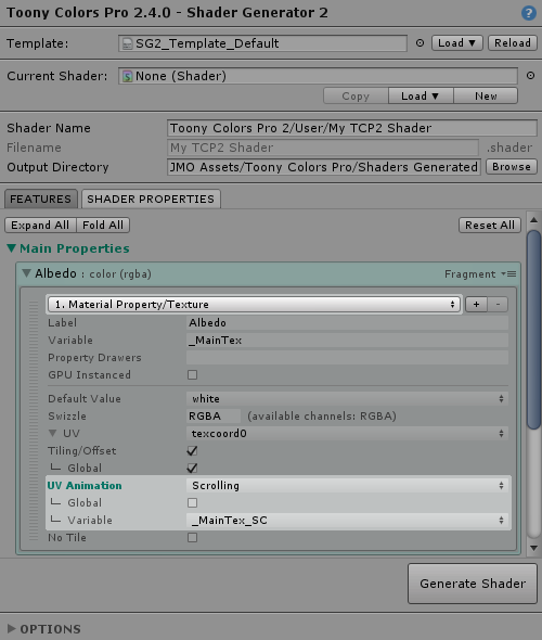
On a *`Material Property/Texture`* implementation, in the *UV* section, set *UV Animation* to *`Scrolling`*.
*Global* will apply the scrolling values to all textures using the same UV, here *`texcoord0`*.
*Variable* allows you to use another texture property's scrolling variable, so that they share their scrolling values (e.g. if you want to scroll a texture and normal map properties synchronously without having to type the same values twice in the material, provided that the Global flag is disabled).
Use Non-Repeating Tiling
========================
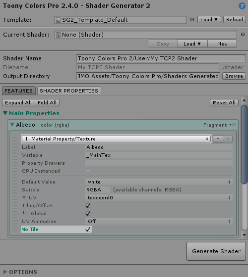
On a *`Material Property/Texture`* implementation, you can enable the *No Tile* option.
This will use a special algorithm to prevent tiled texture repetition.
This algorithm was made by Inigo Quilez ([Technique 3](+http://www.iquilezles.org/www/articles/texturerepetition/texturerepetition.htm), MIT License)
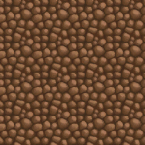
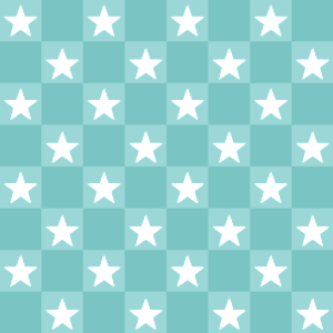
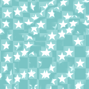
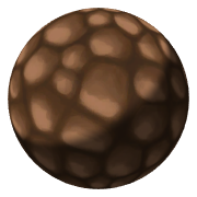
The texture needs to have some randomness to it for the effect to work nicely:
 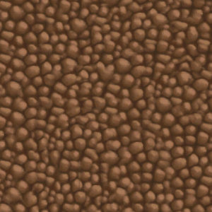
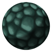
A texture with a regular pattern won't work so well:
Add a Texture mask for any property (e.g. Emission)
===================================================
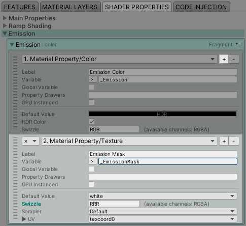
You can setup a texture mask for about any shader property, a typical example being the Emission value.
- Add a new implementation of the type *`Material Property/Texture`*
- Select the mask channel in the *Swizzle* field, for example `RRR` for the red channel (the number of channels to choose will depend on the type of the shader property)
!!! INFO
If your mask is a grayscale texture, make sure to define it as **Single Channel** in its Texture import settings:
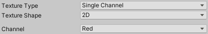
It is better to use **Red** as the color channel, as most platforms can still compress the texture (unlike Alpha only textures).
!!! INFO
You can also apply effects on the texture mask itself (e.g. [UV scrolling](#adduvscrollingtoatexture)) or combine multiple textures together to make some special effects.
For example, this is two texture masks applied to the Emission property: a fixed one, and a scrolling one:

Use triplanar mapping on any texture
====================================
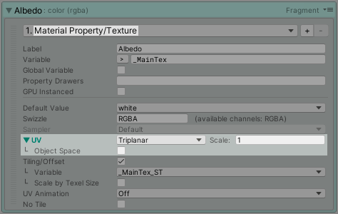
For any shader property that has a *`Material Property/Texture`* implementation, you can change the source UVs.
One of those options is Triplanar, which will sample the texture in world (or object) space across all three X,Y,Z axis, and blend the result together.
Add Hue/Saturation/Value control to any color
=============================================
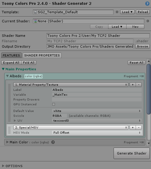
For any `color` or `color (rgba)` shader property, you can add a `Special/HSV` implementation.
This will add hue, saturation and value parameters in the material.
!!! INFO
Use this option sparingly because converting from RGB to HSV and then back to RGB has a cost in the shader, especially on less powerful platforms like mobile.
If possible, you should tweak the color values in the texture file directly, or use the `Saturation Offset` option if it fits your needs, as it is quite fast in comparison.
Keep this option in mind when you need to _dynamically_ change these parameters on your material.
##### Step-by-step Examples
Step-by-step tutorials to achieve specific effects.
Use Vertex Colors as Albedo
===========================
Using vertex colors instead of a texture can save memory on the GPU, and allows you to use the same material for multiple meshes thus making it a good fit for dynamic batching.
--------------------------------
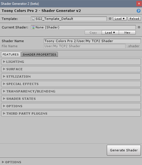
1) Open the Shader Generator 2 through the menu:
`Tools > Toony Colors Pro > Shader Generator 2`
--------------------------------
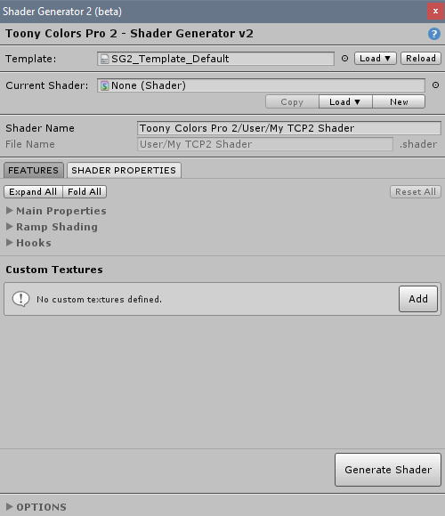
2) Go to the *Shader Properties* tab and expand the *Main Properties* category.
--------------------------------
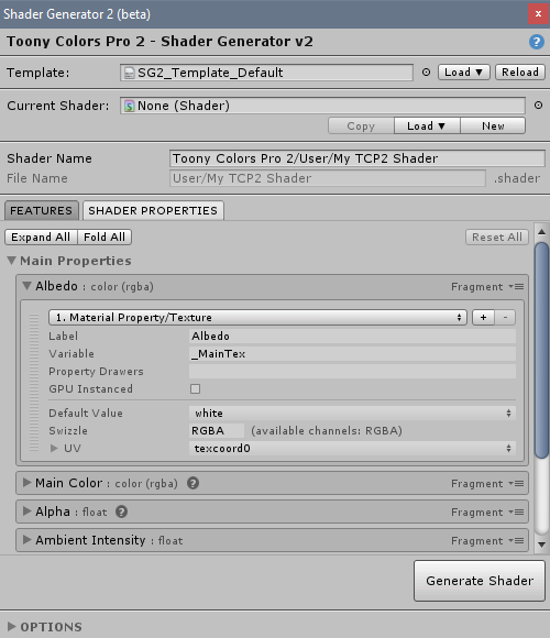
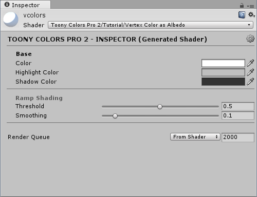
3) Expand the *Albedo* property and click on its only implementation *`1. Material Property/Texture`*, to change it to *`Vertex Color`*.
--------------------------------
4) The property will turn **blue-green**, indicating that its implementation is now different than the default one.
This makes it easy for you to track which properties you have changed.
!!! INFO
The implementations' parameters will also change color if their value is different than the default one.
--------------------------------
5) That's it, you can now click on `Generate Shader`.
The resulting shader will take the mesh's vertex colors for its albedo, instead of a texture.
--------------------------------
Add a detail texture (simple)
=============================
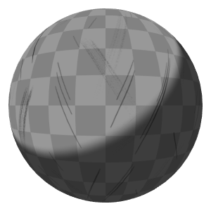
This detail texture will just multiply a monochrome texture on top of the base texture.
--------------------------------
1) In the *Albedo* shader property, add a *`Material Property/Texture`* implementation with the *`+`* button.
Here the *Swizzle* parameter has been set to *`AAAA`*, so that only the alpha channel of the detail texture will be taken into account.
This allows us to import that texture as [single channel](+https://docs.unity3d.com/Manual/TextureTypes.html#SingleChannel) and thus optimize its memory cost.
--------------------------------
Add a detail texture (advanced)
===============================
This advanced detail texture will be alpha blended (i.e. linearly blended based on its alpha channel on top of the base texture), and will also work with a normal map with parallax mapping enabled.
--------------------------------
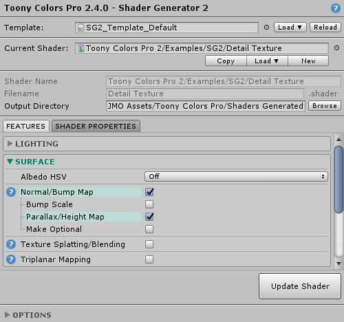
1) We will make this detail texture work with normal maps, so let's enable the required features first:
- Surface:
- Normal/Bump Map: *`✔`*
- Parallax/Height Map: *`✔`*
--------------------------------
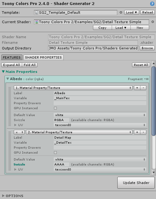
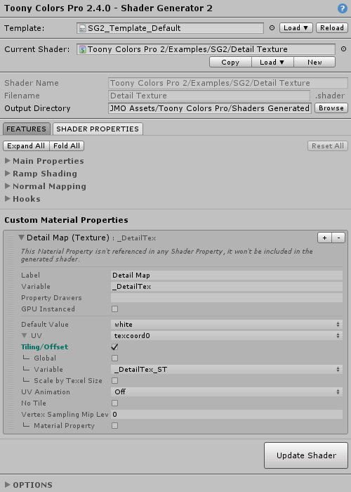
2) Now in the Shader Properties tab, we will create a custom property for the detail texture.
In the *Custom Material Properties* section at the bottom, add a new *`Texture`* property.
Let's call it *`Detail Map`*, and rename its variable to *`_DetailTex`*.
In the *UV* section, enable *Tiling/Offset* so that you can change these values in the material just for the detail texture.
!!! INFO
This texture will use `texcoord0` as the input UVs, meaning that it will share the Albedo property's tiling/offset values.
This is because by default, the Albedo texture is set to use `texcoord0` as well, with the `Global` parameter enabled, meaning that its tiling/offset values are shared with all other textures using `texcoord0`.
Thus the tiling/offset values of the detail texture will be multiplied/added on top of the Albedo tiling/offset values.
--------------------------------
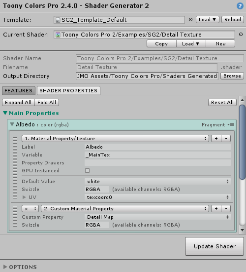
3) We will now reference that texture property we just created.
In the *Main Properties/Albedo* shader property, add a *`Custom Material Property`* implementation and choose the *`Detail Map`* we just created.
--------------------------------
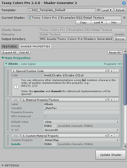
4) By default, the new implementation uses the *`×`* (multiply) operator, but we actually want to alpha blend the texture on top of the base one.
We will insert some custom code for that.
Add a *`Special/Custom Code`* implementation, and drag it at the top of the implementations list so that it's the first one (using the handle bar at the left).
In the code parameter, enter this:
```shader
lerp({2}.rgba, {3}.rgba, {3}.a)
```
Here's what this does:
- The `lerp` function will linearly interpolate between the first argument and the second based on the third one.
- We are referencing other implementations using the {n} notation:
- `{2}` refers to the `Material Property/Texture` implementation, which is our base albedo map
- `{3}` refers to the `Custom Material Property` which is our detail map
In the end, we are interpolating between the base albedo map's colors (`rgba` channels) and the detail map's colors (`rgba` channels) based on the detail map's alpha channel (`a`).
!!! INFO
You may have noticed that the operator options have been disabled, and show `CC` instead.
This is because these implementations are referenced by the custom code node, and their operator will thus be ignored, as the custom code is now responsible for their usage.
This also applies to their swizzle, hence why we manually added the `.rgba` and `.a` swizzle in the custom code.
--------------------------------
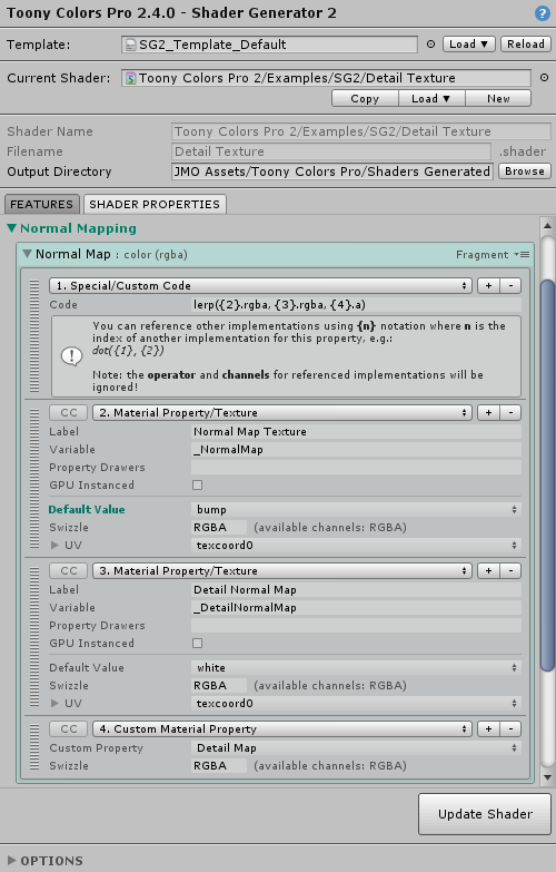
5) Let's do the same for the normal map.
Look into the *Normal Mapping/Normal Map* shader property, and add those implementations:
- *`Special/Custom Code`* as the first one
- *`Material Property/Texture`* which was the original implementation
- *`Material Property/Texture`* which will be the detail normal map (make sure to enable the *`Tiling/Offset`* parameter in the *UV* to replicate the values from the `Detail Map`)
- *`Custom Material Property`* which will reference the *`Detail Map`* we created earlier (and used in the *Albedo* shader property)
The custom code is _almost_ the same as above, except this time we blend between the default `Normal Map Texture` and the new `Detail Normal Map`, still based on the `Detail Map` alpha:
```shader
lerp({2}.rgba, {3}.rgba, {4}.a)
```
!!! INFO
We are linearly blending between two normal maps here, but note that linear blending isn't the most effective way to blend between normals.
You can read this article for more detail: [Blending in Detail](+https://blog.selfshadow.com/publications/blending-in-detail/).
I will investigate ways to implement more advanced blending, as it would be a bit tricky using only one single line of custom code.
--------------------------------
Create a hologram shader
========================
We will create a shader to simulate a hologram, thus we will add some emissive color, transparency, scanlines and distortion effects.
The end result will look like this (with a bloom post-effect):

--------------------------------
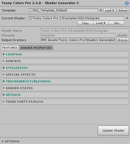
1) Enable the needed [features](+shader_generator_2#featuresreference):
- Lighting:
- Ramp Style: *`No Ramp`*
- Emission: *`✔`*
- Stylization:
- Outline: *`✔`*
- Space: *`Clip Space`*
- Constant-Size: *`✔`*
- Pixel-Perfect: *`✔`*
- Transparency/Blending:
- Blending: *`Additive`*
- Depth pre-pass: *`✔`*
- Options:
- Disable Vertex Lighting: *`✔`*
- One Directional Light: *`✔`*
▪ No ramp prevents the ramp shading calculation, which we don't need since we're going to bypass lighting altogether.
Emission will provide unlit colors, as if the hologram was itself made of light.
▪ Outline in clip space with pixel-perfect option will allow to define its width in pixels, regardless of the mesh distance from the camera, to ensure it always stays crisp and visible.
▪ Additive blending will blend the material's pixel by adding its colors with what's behind, again giving the impression that the hologram is made of light.
Note that the outline will inherit this blending mode and be additive too.
▪ Depth pre-pass will render the mesh once in the depth buffer before actually drawing it, so that we can't see it through itself (see ["Transparent shader with depth writes" here](+https://docs.unity3d.com/Manual/SL-CullAndDepth.html)):
!L[Left: no depth pre-pass, Right: with depth pre-pass](tutorials_data/hologram_depth_prepass.png)
▪ The enabled options (disable vertex lights, one directional light) will ensure that our material has minimal interaction with the scene lights.
--------------------------------
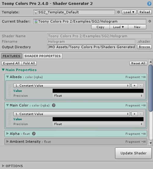
2) Go to the [Shader Properties](+shader_generator_2#shaderproperties) tab.
We will cancel the lighting calculations so that only the emission color is taken into account, and while doing so we will remove all the default material properties that would otherwise show up in the material inspector.
For both *Albedo* and *Main Color* in *Main Properties*, replace the default implementations with a *`Constant Value`*, and set their values to *black* (and *alpha to 0*).
!!! INFO
Not only will this remove the albedo texture and main color from the material inspector, setting a value of (0,0,0,0) will also help the compiler to optimize the resulting code: by knowing that a result will eventually be multiplied by zero, the shader compiler is able to strip out unnecessary calculations in the compiled code.
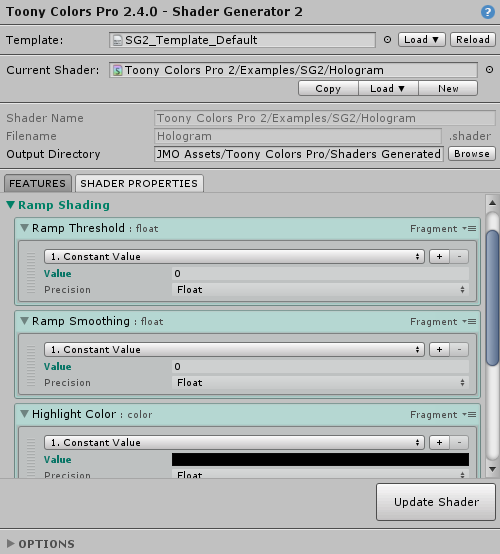
--------------------------------
3) In the *Ramp Shading* section, do the same for all 4 properties:
- Ramp Threshold: `Constant Value` -> 0
- Ramp Smoothing: `Constant Value` -> 0
- Highlight Color: `Constant Value` -> black
- Shadow Color: `Constant Value` -> black
!!! INFO
Removing lighting from a lit shader that way isn't the best thing to do, but please note that I do plan to add a proper unlit option eventually.
--------------------------------
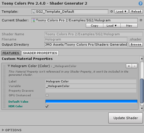
4) We will now create a custom property that will control our hologram color.
In the *Custom Material Properties* section, add a new *`Color`* property.
Name it *`Hologram Color`*, and optionally rename its variable to *`_HologramColor`* if you care about the generated shader code readability.
Set a light blue color as the *Default Value*, and optionally enable *HDR Color* (can be useful when using bloom).
--------------------------------
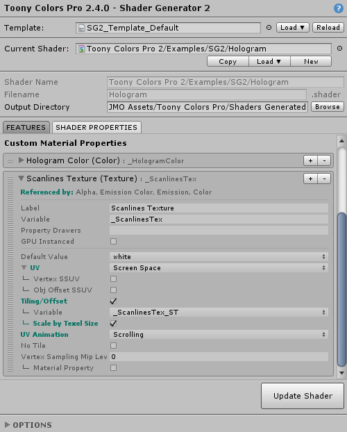
5) We will also create a texture property to create a scanlines effect, like in old CRT televisions.
Still in the *Custom Material Properties* section, add a new *`Texture`* property.
Name it *`Scanlines Texture`* and rename its variable accordingly.
We want the scanlines to always be horizontal, no matter the view angle, so we will use screen-aligned UV coordinates.
Set the *UV* to *`Screen Space`*, and expand its options:
- *Tiling/Offset*: *`✔`*
- *Scale by Texel Size*: *`✔`* - this will scale the UVs so that the texture will use its native size regardless of the screen resolution (provided that the XY tiling values stay at 1,1); in the provided example, the scanlines will always be 2 pixels tall.
- *UV Animation*: *`Scrolling`* - so that we can scroll the scanline texture upwards to enhance the effect
--------------------------------
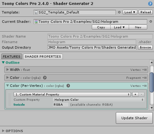
6) We will now use those custom material properties in our shader.
Open the *Outline* group, and in the *`Color (Per-Vertex)`* shader property, replace the default implementation with *`Custom Material Property/Hologram Color`*.
This will make the outline color use the hologram color property we defined earlier.
--------------------------------
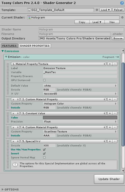
7) Now let's edit the emission color.
Open the *Emission* group, and the Emission shader property:
- Replace the default *`Material Property/Color`* implementation with a *`Material Property/Texture`*, and rename its variable to *`_MainTex`*.
We will use the albedo texture for the emission color. Renaming the variable will allow the material to keep its albedo texture when switching to this hologram shader.
- Add a new implementation: *`Custom Material Property/Hologram Color`*, so that the texture gets multiplied with the hologram color we defined earlier.
- Add a new implementation: *`Constant Value`*, and set it to a medium gray (0.5, 0.5, 0.5). This will divide the hologram color by two, so that its intensity is half of the outline's color.
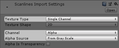
- Add a new implementation: *`Custom Material Property/Scanlines Texture`*, and set its *Swizzle* to *`AAA`*, so that we only use the alpha channel of the scanlines texture.
This is because the scanline texture has been imported as a single-channel texture using the alpha channel only:
- Finally, add this implementation: *`Special/N·V`*, which will be multiplied with all the rest. It will make the 'inner' parts of the mesh transparent, depending on the view angle. See the [documentation about special implementations](+shader_generator_2#shaderproperties/implementationsreference/special/...) for more information.
Enable *`Use Min/Max Properties`* to be able to tweak the effect, and *`Invert`*.
Since we're using an additive blending mode, the black parts of the N·V calculation will effectively mask out the material.
--------------------------------
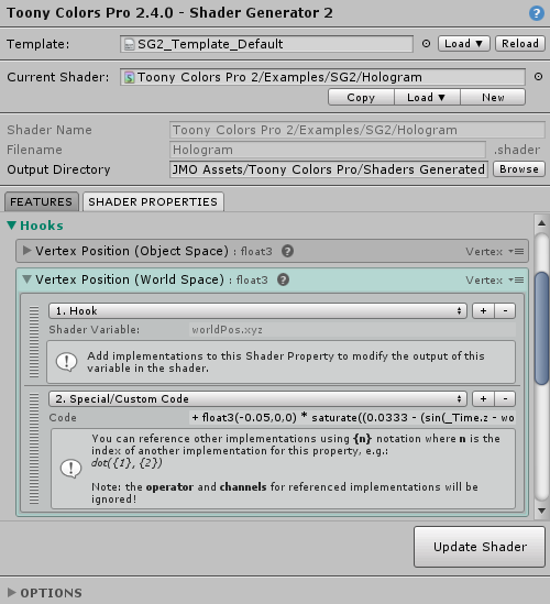
8) We will now create a scanline distortion effect by using the [Custom Code implementation](+shader_generator_2#shaderproperties/implementationsreference/special/customcode) with the Vertex Position hook.
Open the *Hooks* group, and look for the *Vertex Position (World Space)* shader property.
Add a *`Special/Custom Code`* implementation, and set it to this:
```shader
+ float3(-0.05,0,0) * saturate((0.0333 - (sin(_Time.z - worldPos.y*5)+1)*0.5)*30)
```
Here's what this code does, decomposed from left to right:
- `+` : the custom code is appended right after the `worldPos` variable from the hook, so we need to define how it will affect it
- `float3(-0.05,0,0) * ` : you can think of this as a mask, so that only the X component of the world vertex position will be slightly altered by the code
- `saturate` : this function is equivalent to `clamp(x, 0, 1)`, that is, it will force the value to be within the [0-1] range
- `(0.0333 - (sin(_Time.z - worldPos.y*5)+1)*0.5) * 30` : we calculate a steep sine wave, which will give a 'dents' graph because of the saturate function above. You can visualize it on this graphing tool. The `_Time.z` as an offset of the sine function is what makes the effect move.
In the end, this code will displace the vertices on their X axis based on their Y position in world space over time.
--------------------------------
9) You should end up with this result (here using a bloom post effect and a HDR hologram color).

--------------------------------
Create an advanced dissolve shader
==================================
We will create an advanced dissolve shader, that will work nicely regardless of the mesh UV, with some texture and vertex animation to enhance the effect.
The end result will look like this (with a bloom post-effect):

--------------------------------
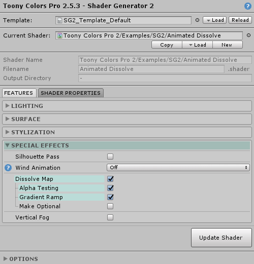
1) Enable the needed [features](+shader_generator_2#featuresreference):
- Special Effects:
- Dissolve Map: *`✔`*
- Alpha Testing: *`✔`*
- Gradient Ramp: *`✔`*
▪ *Alpha Testing* will make the mesh transparent in the areas that are completely dissolved
▪ *Gradient Ramp* will apply a color on the edge of the dissolution effect
--------------------------------
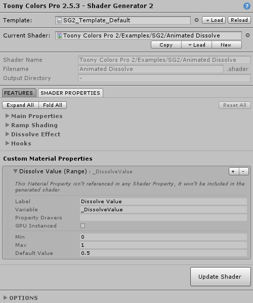
2) Go to the [Shader Properties](+shader_generator_2#shaderproperties) tab.
We will create a custom property that will drive the dissolve animation.
Look for the *Custom Material Properties* section, and add a *Range* one.
Set it up so that it looks like this:
- Label: *`Dissolve Value`*
- Variable: *`_DissolveValue`*
- Min: *`0`*
- Max: *`1`*
This will add a slider property in our shader, that goes from 0 to 1.
0 will be no dissolution, and 1 will be fully dissolved.
--------------------------------
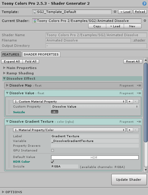
3) Let's use this new property.
In the *Shader Properties*, look for the *Dissolve Effect* section.
Open the *Dissolve Value* property, and replace the existing *`Material Property/Range`* to *`Custom Material Property/Dissolve Value`*.
This will replace the default property with the one we just created earlier.
Open the *Dissolve Gradient Texture* property, and replace the existing *`Material Property/Texture`* to *`Material Property/Color`*.
Then enable the *HDR* flag.
This will allow us to use a simple color rather than having to author a texture for the dissolution edge.
The HDR flag will allow us to use HDR values, and thus get nice hue variations in addition to the shader working well with a bloom post process effect.
--------------------------------
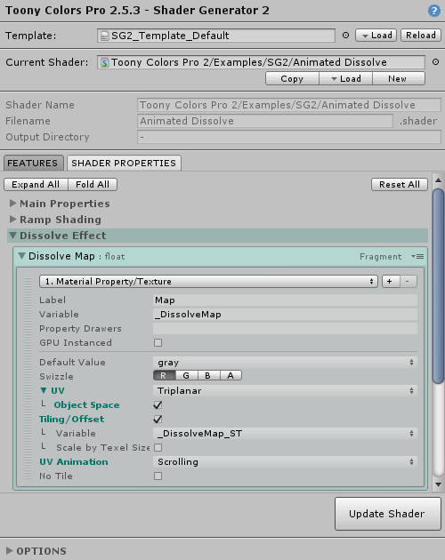
4) Open the *Dissolve Map* property.
Change the *UV* to *`Triplanar`*, this will ensure that the dissolve pattern will always look nice for all meshes, regardless of their UVs.
Open the *UV* section, and change those settings:
- Object Space: *`✔`*
- Tiling/Offset: *`✔`*
- UV Animation: *`Scrolling`*
Having *Triplanar* in *Object Space* makes the UVs consistent with the object's transform, rather than with the world, such that when the object moves, the dissolve pattern stays in place.
The *Tiling/Offset* values will allow us to scale the dissolve pattern.
The *UV Scrolling Animation* will add some movement to the dissolution effect.
--------------------------------
5) Now let's add some vertex displacement.
We will make it so that vertices will stretch on the vertical axis as the dissolution increases.
Combined with the transparent effect, it will look like the remaining bits are floating away in space before disappearing entirely.
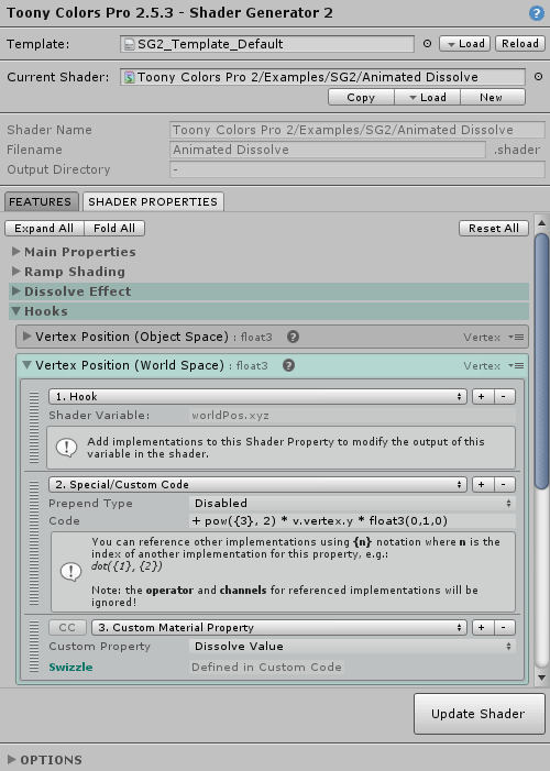
In the *Shader Properties*, look for the *Hooks* section, and open the *Vertrex Position (World Space)* hook.
In the implementations list, add a *`Special/Custom Code`* one, and then a *`Custom Material Property/Dissolve Value`* after it, using the `+` buttons.
Then in the *Code* field, enter this:
- **Built-in Render Pipeline:**
```shader
+ pow({3}, 2) * v.vertex.y * float3(0,1,0)
```
- **Universal Render Pipeline (URP):**
```shader
+ pow({3}, 2) * input.vertex.y * float3(0,1,0)
```
Here's what this code does, decomposed from left to right:
- `+` : the custom code is appended right after the `worldPos` variable from the hook, so we need to define how it will affect it
- `{3}` : this is a reference to the third implementation of the property, in this case the `Custom Material Property/Dissolve Value`
- `pow({3}, 2)` : we apply a power of 2 to that value, so that instead of having a linear effect, it will get stronger as it reaches its end value
- `* v.vertex.y` : multiply the new dissolve value by the Y position of the vertex in object space, so that vertices that are further away from the object's origin are more affected by the displacement
- `* float3(0,1,0)` : you can think of this as a mask, so that only the Y component of the world vertex position will be affected by this code
--------------------------------
6) You should end up with this result (here using a bloom post effect and a HDR dissolve color).
Here the *Dissolve Value* is animated from 0 to 1, and back.
You can see the material used and its settings in the *Demo TCP2 ShaderGenerator 2* scene.

--------------------------------
Create a custom Terrain shader
=================================================
We will create an shader that is compatible with Unity's terrain system, with some per-layer customization on top of it.
--------------------------------
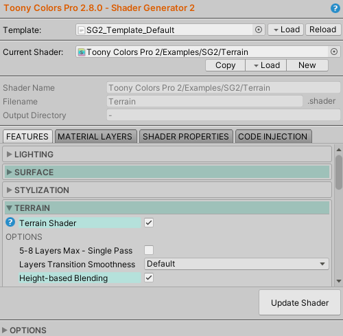
1) Enable the needed [features](+shader_generator_2#featuresreference):
- Surface:
- Terrain Shader: *`✔`*
- OPTIONS:
- Height-based Blending: *`✔`*
▪ *Terrain Shader* will ensure compatibility with the terrain shader, by generating 4 .shader files _(main shader, AddPass, BaseGen, BasePass)_ and replacing the default Albedo texture with the texture layers provided by the terrain system.
▪ *Height-based Blending* will apply an algorithm to blend each layer based on a height map.
Additionally, you can enable normal mapping to support the terrain layers Normal Maps.
- Surface:
- Normal/Bump Map: *`✔`*
--------------------------------
2) We will customize how some of the layers are sampled.
Go to the [Shader Properties](+shader_generator_2#shaderproperties) tab.
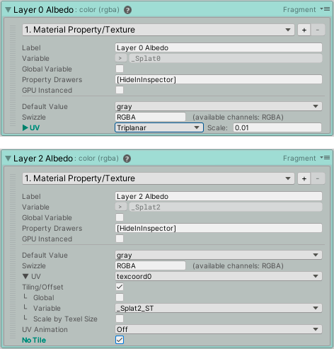
Open the *Terrain* section, and look for the *Layer 0 Albedo* property.
Let's say this layer will use a rocks texture and thus be used for mountains, it would be a great candidate to enable *triplanar mapping* on.
Open the property, and on its UV parameter, change from *texcoord0* to *Triplanar*.
Let's also edit the *Layer 2 Albedo* property so that it uses [non-repeating tiling](+shader_generator_2#shaderproperties/implementationsreference/materialproperty/.../materialproperty/texture//notiledetails), by toggling the *No Tile* option in the expanded UV options.
After those changes, the *first* and *third* textures of your terrain will respectively use *triplanar mapping* and *non-repeating tiling*.
!!! INFO
You will most likely want to apply the same options for the *Layer 0/2 Mask* and *Layer 0/2 Normal Map* properties so that their pixels will exactly match the sampling of their Albedo counterpart.
!!! WARNING
If you are using *multiple terrains* connected to each other, make sure that the textures using special options like the ones we just toggled are always *at the same position* in the list of the terrain's layers, else you might end up with a different texture being sampled incorrectly.
Unfortunately those kind of options can't be determined per terrain layer directly (see the [terrain index vs. terrain layers paragraph](+shader_generator_2#featuresreference/terrain/terrainshader/noteontheterrainshaderpropertiesvs.terrainlayers) to know why).
--------------------------------
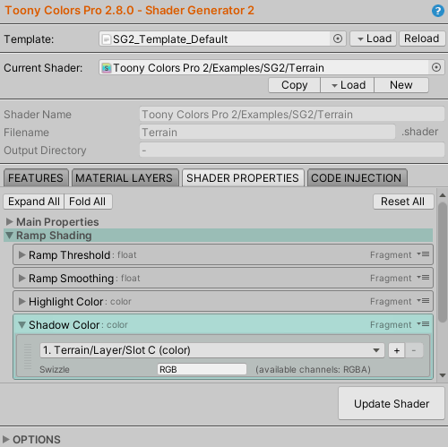
3) We will now customize some properties so that they will be controllable per terrain layer.
Open the *Ramp Shading/Shadow Color* property, and click on the default *Material Property/Color* implementation to replace it with *Terrain/Layer/Slot C (color)*.
Now each layer will have a color that will be used as the *shadow color* in the shader.
The custom interface of the layer in the terrain inspector will be updated accordingly, with the correct label "Shadow Color" (if the *Auto Label* option was left enabled for the *Slot C (Color)* in the *Features* tab):
!L[ ](tutorials_data/terrain_3_layers.png)
!!! WARNING
The custom interface only works within the **Terrain inspector**.
It **will not work** when selecting individual Terrain Layer assets in the Project window.
--------------------------------
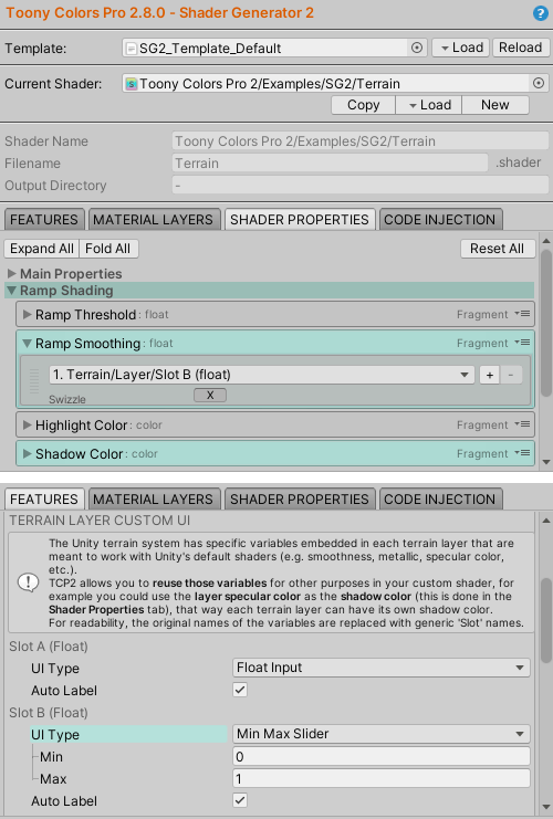
4) Let's do the same for the *Ramp Shading/Ramp Smoothing* property.
Replace its default implementation with *Terrain/Layer/Slot B (float)*.
Go back to the *Features* tab, and set this option:
- Terrain:
- TERRAIN LAYER CUSTOM UI:
- Slot B (Float):
- UI Type: *`Min Max Slider`*
and leave the *Min* and *Max* values at 0 and 1 respectively.
Because the Ramp Smoothing expects a value between 0 and 1, this will ensure that we cannot set another value by showing a slider instead of a free float input:
!L[ ](tutorials_data/terrain_4_layers.png)
--------------------------------
5) Your terrain shader is ready!
You can use the other [Terrain implementations](+shader_generator_2#shaderproperties/implementationsreference/terrain/...) similarly to customize your shader further!
You can go even more in depth combining them with the other implementations from the [Shader Property system](+shader_generator_2#shaderproperties).
--------------------------------
#####
Contact
=======
If you have questions, bug reports or suggestions please contact me by email at: jean.moreno.public+unity@gmail.com